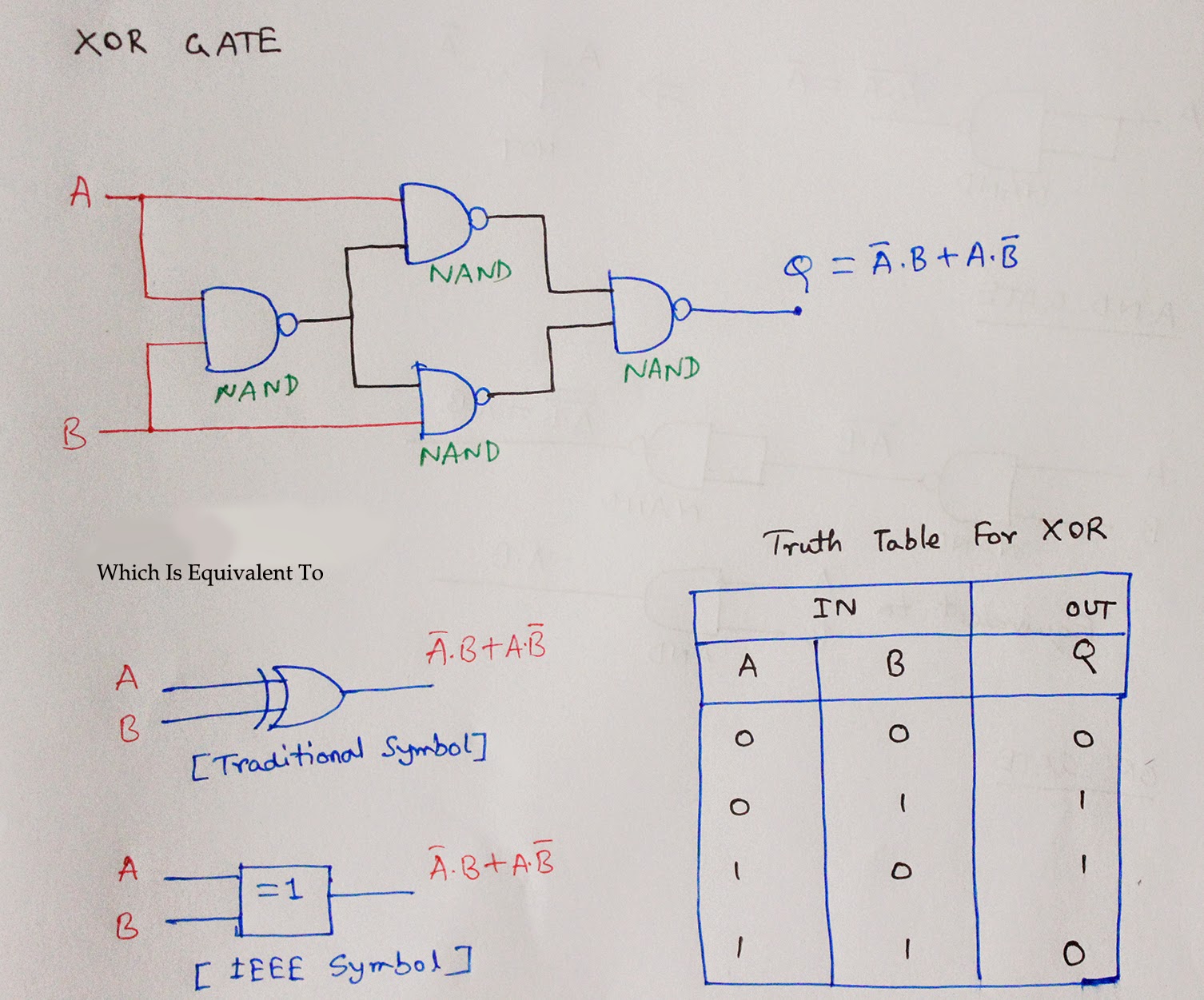
Nand Gate Truth Table And Circuit Diagram
What is sr flip flop? truth table, circuit diagram explained Truth table logic gates 3 inputs [diagram] logic diagram of nand gate
d flip flop circuit diagram and truth table - Wiring Diagram and Schematics
Settlers motto auction 3 input nand gate truth table see through Zamat vír ozón rs flip flop generator darebák dať monopol A) shows the logic symbol used to identify the d-latch. the operation
Nand gates nor xnor circuit vhdl xor logic verify simulate truth circuits tutorial basic ckt
Nand gate logic diagram[diagram] circut diagram nand gate Cmos nand gate circuit diagram[diagram] circuit diagram nand gate.
Nand gate truth table3 input nand gate circuit diagram Adder full nand truth diagram table logic using gate minimum number implementingD flip flop circuit diagram and truth table.

Form 4 it genius: nand & nor gates
[diagram] circuit diagram nand gateNand gate truth table input tables electronics Latch logic operation truth nand gates booleanFull adder.
Digital electronics-logic gates basics,tutorial,circuit symbols,truthIntroduction to logic gates Nand gate circuit diagramCircuit diagram of nand logic gate.

Truth table for logic gates with 3 inputs
Nand gate truth table 2 inputs3-input or gate truth table. Nand nor gates gate input truth table inputs ic output comparator sense differential dual speed amp high genius formTruth table for logic gates with 3 inputs – two birds home.
Truth logic inputs gates3 input xor gate truth table Truth gate nand table input logic gates circuit symbol two tables diagram inverter digital draw not give symbols junction explainVhdl tutorial – 5: design, simulate and verify nand, nor, xor and xnor.

Logic gates-electron-fmuser fm/tv broadcast one-stop
[diagram] logic diagram using nand gateSolved 1. design a circuit using only nand gates that 46+ circuit diagram of half adder using nand gateCircuit diagram of nand logic gate.
Circuit diagram of not gate using nand wiring view anHow to draw a circuit diagram with truth table Truth table for nor gate with 4 inputs2 input nand gate circuit diagram.


Truth Table For Logic Gates With 3 Inputs – Two Birds Home
 Input Logic Gates with Truth Table.png)
How To Draw A Circuit Diagram With Truth Table | Porn Sex Picture

3 Input Nand Gate Circuit Diagram
![[DIAGRAM] Circut Diagram Nand Gate - MYDIAGRAM.ONLINE](https://i.ytimg.com/vi/DsPet6URykQ/maxresdefault.jpg)
[DIAGRAM] Circut Diagram Nand Gate - MYDIAGRAM.ONLINE

2 Input Nand Gate Circuit Diagram

Truth Table For Logic Gates With 3 Inputs | Two Birds Home

Circuit Diagram Of Not Gate Using Nand Wiring View An - vrogue.co

Nand Gate Logic Diagram